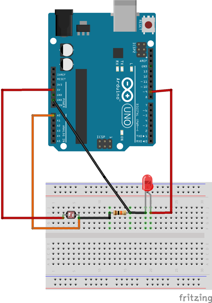
How To Make Light Sensitive Automatic On Off Light Circuit Diagram Before you use the actual code, find out the value of the LDR for different brightness levels. This can be done by using the AnalogRead program in the example sketches. If you're wondering how the brightness gets adjusted, then go through the Fade program in the examples. Once you have the values, map it to the code and upload it. Here, I'll be

In this project, we are going to make a circuit for Motion Sensor Activated Light With Automatic Brightness Adjustment using Arduino, PIR & LDR sensors.Intro
Led Brightness Control Using Ldr With Cloudx Circuit Diagram
In this project, we are going to make a PIR based motion sensor activated light and using an LDR (photoresistor) to automatically adjust the brightness of the light ie at night the light will be in full brightness and in the morning if the sunlight is low then the light will automatically turn on with a suitable brightness if motion is detected.

Build the above circuit using the schematic shown above. Connect the LED strip or a 12V LED from the 1K resistor to GND. To test, plug in a 12V 1A (center positive) AC/DC power adapter into the 2.1mm DC power jack, and try waving your hand over the LDR to make the area darker. If the LED brightness changes, then the circuit is working.

Motion Sensor Activated Light With Automatic Brightness Adjustment ... Circuit Diagram
In case B, the photoresistor is mapped to different brightness levels of the LEDs. Thus, we map the light level values from the photoresistor to the desired brightness range for the LED(s). Use the analogWrite() function to control the LED(s) brightness by supplying the appropriate PWM (Pulse Width Modulation) value. Figure 6: Code for Case A